
Views: 0 Author: Site Editor Publish Time: 2026-08-10 Origin: Site


Electroplating facilities face strict environmental regulations regarding heavy metal discharge and high costs for off-site hazardous waste disposal. Traditional chemical precipitation and membrane filtration concentrate the waste but fail to eliminate liquid discharge entirely. This leaves your plant vulnerable to compliance fines and rising disposal fees for transporting concentrated brine. Achieving true Zero Liquid Discharge (ZLD) requires transitioning from simple volume reduction to complete phase separation. You accomplish this through advanced thermal and mechanical processes. Specifically, utilizing MVR evaporation and crystallization followed by centrifuge dewatering allows you to recover clean water and isolate solid salts for safe disposal or recovery. We see many plants struggle with the final step of brine management. By implementing these thermal and mechanical systems, you stop paying to haul water and start recovering valuable resources directly on-site.
Regulatory & Financial De-risking: Implementing ZLD eliminates liquid discharge compliance risks and drastically reduces hazardous waste hauling volumes.
Energy Efficiency is Critical: Mechanical Vapor Recompression (MVR) evaporation & crystallization reduces energy consumption by recycling latent heat, offering a lower OPEX alternative to traditional multi-effect evaporators.
Material Integrity: Electroplating wastewater is highly corrosive (chlorides, sulfates, heavy metals); system longevity depends on specifying high-grade alloys (e.g., Titanium, Duplex stainless steel) for evaporators and centrifuges.
The Two Outputs of Complete Separation: The final step of ZLD relies on a high-performance centrifuge to efficiently separate crystallized solids from the mother liquor, ensuring the system produces only two distinct outputs: high-purity reusable water and dry solid waste.
Table of Contents
When you evaluate a ZLD investment, you need to look at daily effluent volume, local discharge limits, and your current cost per ton for liquid waste disposal. Plants generating high volumes of concentrated brine find that hauling liquid waste off-site drains budgets fast. Once disposal costs cross a specific threshold, thermal separation equipment becomes a necessary operational shift. The main success metric is zero liquid waste leaving your facility boundaries.
You must evaluate whether you need absolute Zero Liquid Discharge or if Minimal Liquid Discharge (MLD) works better for your specific site. MLD reduces wastewater volume by up to 95% using advanced membrane technologies. However, it leaves a highly concentrated liquid fraction requiring specialized disposal. Local regulations dictate this choice. In regions with strict municipal sewer limits, MLD falls short. Absolute ZLD becomes mandatory to keep your operating permits active.
Resource recovery adds another layer to the project. Electroplating wastewater contains metals like nickel, copper, and chromium. While recovering solid metals presents an opportunity, the most significant resource you recover is the water itself. High-performance thermal systems recycle up to 95% of the wastewater as high-purity distillate. You route this recovered water directly back into the rinsing process. This drastically reduces municipal water intake and lowers overall facility water consumption.
Parameter | Minimal Liquid Discharge (MLD) | Zero Liquid Discharge (ZLD) |
|---|---|---|
Volume Reduction | Up to 95% | 100% (Complete phase separation) |
Final Output | Highly concentrated liquid brine | Dry solid salt cake and pure distillate |
Regulatory Compliance | Subject to local sewer discharge limits | Eliminates all liquid discharge liabilities |
Primary Technology | Reverse Osmosis (RO), Ultrafiltration | MVR Evaporation, Crystallization, Centrifuge |
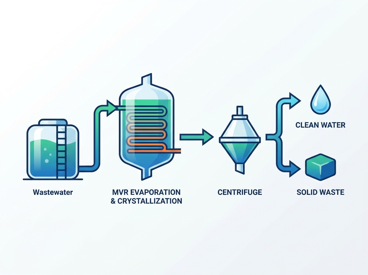
Wastewater Collection and Comprehensive Analysis: The first step involves characterizing the specific plating bath chemistry. Electroplating facilities utilize diverse baths, including cyanide, acid copper, and hexavalent chromium. You must establish baseline parameters for the entire treatment train using techniques like ICP-OES for heavy metal profiling. Accurate profiling of total dissolved solids (TDS), chemical oxygen demand (COD), and specific ion concentrations dictates the design of downstream thermal and mechanical equipment.
Primary and Secondary Treatment (Physical & Chemical): Upstream processes prepare the wastewater for thermal processing. For example, if your line runs hexavalent chromium, you must first reduce it to trivalent chromium using sodium metabisulfite at a low pH before any precipitation can occur. Similarly, cyanide-bearing wastes require alkaline chlorination to destroy the cyanide compounds completely. Following these destruction steps, you typically include pH adjustment, polymer addition for flocculation, and clarification. Next, ultrafiltration and Reverse Osmosis (RO) concentrate the effluent. RO membranes remove clean water and reduce the volumetric load on downstream thermal systems.
The Brine Challenge and Thermal Intervention: As RO systems concentrate the wastewater, they hit an osmotic pressure limit around 80,000 to 120,000 mg/L TDS. Standard high-pressure pumps cannot push water through membranes beyond this point. The resulting highly concentrated brine requires a transition to thermal technologies. Membrane systems alone cannot achieve phase separation; they only divide the water into a clean stream and a concentrated liquid stream.
MVR Evaporation & Crystallization: The sequential flow moves to thermal concentration. The brine enters the thermal system, pushing past pre-concentration into full evaporation. You drive off the remaining water, pushing the brine past its saturation point. Once saturation is breached, dissolved salts precipitate, forming solid crystals suspended in a thick slurry.
Final Solid-Liquid Separation: The final step relies on mechanical dewatering. You cannot dispose of the slurry in its wet state. Mechanical force extracts the remaining liquid from the solid crystals. This results in the final binary outputs: high-purity condensed water and a dry solid waste cake ready for compliant disposal or secondary metal recovery.
Mechanical Vapor Recompression operates on a highly efficient thermodynamic principle. Instead of relying on external steam to boil the wastewater, MVR captures the secondary vapor generated during the evaporation process. A mechanical compressor then compresses this vapor, increasing its temperature and pressure. Depending on the vapor volume, you will typically select either a Roots-type lobe compressor for smaller flows or a high-speed centrifugal compressor for massive evaporation rates. You route this compressed, higher-energy vapor back into the heat exchanger to serve as the heating medium for the incoming wastewater. The system continuously recycles the latent heat of vaporization.
When comparing MVR efficiency against traditional steam-driven Multi-Effect Evaporation (MEE) in plating wastewater applications, the operational differences stand out. MEE requires a continuous supply of live steam from an industrial boiler, consuming massive amounts of natural gas or fuel oil. MVR replaces the boiler requirement with electrical power to drive the compressor. In areas with stable electrical grids, MVR drastically lowers the thermal energy required per ton of evaporated water.
Managing the transition from concentrated brine to a slurry of suspended solid crystals requires precise control over the saturation point. As water evaporates, the concentration of dissolved salts increases until the solution reaches supersaturation. At this specific point, nucleation occurs, and solid crystals begin to form. You must manage this phase change carefully to prevent salts from scaling on the heat exchanger tubes.
Advanced one-step crystallization technology can bypass multi-stage evaporation for highly concentrated, low-volume effluents. In specific ZLD and MLD applications where the feed wastewater is already near saturation, routing the effluent directly into a crystallizer simplifies the process train. This approach minimizes equipment footprint and reduces the complexity of managing multiple evaporation effects.
Crystallizer design dictates how well you handle high-viscosity plating effluents without plugging. Forced circulation crystallizers utilize massive axial flow pumps to push the brine through the heat exchanger at high velocities. This high velocity prevents boiling inside the tubes. Instead, boiling and crystallization occur only when the superheated liquid flashes into the main separator vessel. This design keeps the heat transfer surfaces clean and forces crystal growth in the bulk fluid.
Evaluating the operational expenses of thermal systems requires comparing the electrical load of the MVR compressor against the boiler fuel requirements of steam-driven systems. MVR compressors consume electricity, making their operational viability dependent on local power rates. However, the energy required to compress vapor is a fraction of the energy required to generate fresh steam. This makes MVR highly efficient for continuous, high-volume operations.
Integrating a complete MVR Evaporation & Crystallization,Centrifuge system requires assessing footprint requirements and infrastructure. MVR systems often feature a vertical design, utilizing falling film evaporators to maximize heat transfer while minimizing floor space. Continuous MVR operation demands a highly stable electrical grid. Voltage drops or power interruptions can trip the compressor, disrupting the delicate thermal balance and requiring a full system restart.

The mechanical process of dewatering begins when the centrifuge receives the thick slurry from the crystallizer. This slurry consists of solid salt crystals suspended in a highly concentrated liquid known as the mother liquor. The centrifuge applies extreme centrifugal force to separate the heavier solid particles from the lighter liquid phase. Industrial centrifuges applied in these environments typically generate between 2,000 and 3,000 Gs. This massive force drives the residual moisture content of the salt cake down to 5% or less, depending on the crystal structure.
Once separated, you route the outputs to their respective destinations. The centrifuge discharges a dry salt cake, which falls into a collection bin or conveyor for final disposal or off-site recovery. You collect the extracted mother liquor, which still contains dissolved organics and highly soluble salts that did not crystallize, and recycle it back into the crystallizer loop to undergo further thermal processing.
Choosing the correct centrifuge involves evaluating particle size, required cake dryness, and continuous operation capabilities. Decanter centrifuges utilize a solid cylindrical bowl and an internal scroll conveyor. They excel at handling varying particle sizes and fluctuating feed concentrations, making them highly versatile for complex plating wastewater. Pusher centrifuges use a wedge wire screen and a reciprocating piston. They achieve exceptional cake dryness and allow for crystal washing, but they require larger, uniform crystal sizes to prevent solids from passing through the screen.
Material specification is an absolute necessity when processing acidic or chloride-rich plating waste. The high rotational speeds of a centrifuge create significant mechanical stress, which accelerates corrosion if you use the wrong metallurgy. Standard stainless steel rapidly degrades under high chloride concentrations. You must construct centrifuge bowls, scrolls, and screens from highly corrosion-resistant materials such as Hastelloy, Titanium, or high-grade Duplex stainless steel to ensure mechanical integrity and prevent catastrophic failure.
Centrifuge maintenance in corrosive environments requires strict adherence to wash cycles. After every production run, operators must flush the bowl and scroll with clean condensate to remove residual salts. If left stagnant, wet chloride salts will initiate localized pitting, even on high-grade alloys. You also need to monitor the hard-facing on the scroll flights. The abrasive nature of crystallized salts will eventually wear down the tungsten carbide tiles or Stellite hard-facing, requiring factory rebuilds to maintain separation efficiency.
Mapping the relationship between specific plating chemistries and required metallurgy dictates system longevity. Wastewater containing high levels of chlorides—common in acid zinc or nickel plating—causes severe pitting and stress corrosion cracking in standard 304 or 316 stainless steels. For these applications, you require Titanium Grade 2 or Grade 7 for heat exchanger tubes and wetted vessels. Conversely, wastewater dominated by sulfates without halogens may allow the use of Duplex 2205 or Super Duplex 2507. This optimizes material costs without sacrificing durability.
You must assess whether modular or custom-built ZLD systems fit your physical constraints. Modular systems arrive pre-piped and pre-wired on structural skids, drastically reducing on-site installation time. For facilities with limited floor space, vertical MVR designs utilize tall falling film evaporators that expand upward rather than outward. You can integrate compact centrifuge skids directly beneath the crystallizer discharge. This utilizes gravity to feed the slurry and minimizes the need for intermediate transfer pumps.
Modern thermal separation relies heavily on PLC-based control systems integrated with plant SCADA networks to minimize manual oversight. Human operators cannot react fast enough to the rapid thermodynamic changes inside an evaporator. Automated sensors continuously monitor boiling point elevation (BPE), adjusting feed rates and steam input to maintain optimal supersaturation. Vibration sensors on the MVR compressor and torque monitors on the centrifuge scroll detect mechanical anomalies instantly. They trigger automated shutdowns to prevent equipment damage before operators even notice a problem.
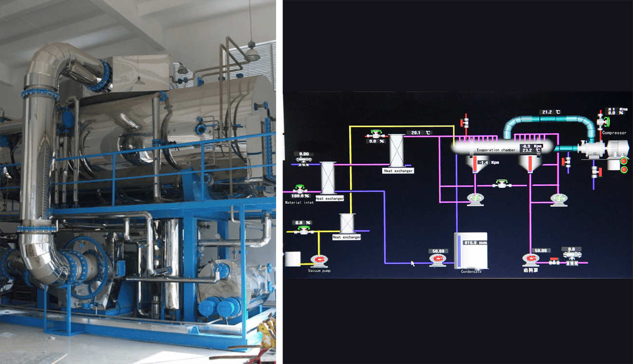
Calcium, magnesium, and silica present in plating water pose a severe scaling risk. These compounds often exhibit inverse solubility, meaning they become less soluble as temperature increases. They precipitate directly onto the hot heat transfer tubes, forming a hard insulating layer. This drastically reduces MVR efficiency and forces the compressor to work harder. Silica is particularly troublesome because it forms a glass-like scale that resists standard acid washing, often requiring hazardous hydrofluoric acid or mechanical drilling to remove if allowed to bake onto the tubes.
Mitigation requires strict upstream softening to remove hardness before the water enters the thermal system. Additionally, implementing regular automated Clean-in-Place (CIP) protocols using acid or alkaline washes dissolves early scale formation. Utilizing forced circulation designs maintains high tube velocity, physically scouring the tube walls and preventing scale from taking hold.
A major risk in closed-loop crystallization is the accumulation of highly soluble, non-crystallizing organics and hygroscopic salts in the crystallizer loop. Because these compounds do not form solid crystals easily, they build up in the mother liquor. This increases the boiling point elevation until the compressor can no longer drive evaporation.
To prevent system degradation, you must establish a calculated bleed stream. You continuously or batch-purge a small percentage of the mother liquor from the loop. You then route this bleed stream to a secondary agitated thin-film dryer for final reduction or send it off-site for specialized disposal, keeping the main crystallizer chemistry balanced.
Electroplating facilities frequently switch finishes or alter production lines, causing rapid changes in the wastewater composition. A sudden spike in organic additives or a shift in pH can upset the crystallization curve, causing foaming in the evaporator or producing fine, un-centrifugeable crystals.
Mitigation relies on robust equalization. You must route wastewater into large equalization tanks with sufficient retention time—often 24 to 48 hours—to homogenize the feed. Continuous agitation inside these tanks ensures that spikes in chemistry are diluted and blended. This provides the MVR system with a consistent, predictable feed profile.
Initiate a comprehensive laboratory-scale brine characterization to identify specific boiling point elevations and scaling risks associated with your unique plating bath chemistry.
Conduct pilot testing using a slipstream of your actual wastewater to validate crystallization behavior and prove centrifuge separation efficiency under real-world conditions.
Audit your facility's electrical grid stability and capacity to ensure it can support the continuous, high-amperage draw required by an MVR compressor without voltage drops.
Specify exact metallurgical requirements for all wetted components based on the chloride and sulfate concentrations identified during the initial water analysis to prevent premature corrosion.
VNOR develops and manufactures evaporation and crystallization systems, including MVR, multi-effect, and heat-pump evaporators, for wastewater treatment and other process industries. Its team supports projects from system design and fabrication through installation, commissioning, and after-sales service.FAQ
A: Evaporation removes water to concentrate the wastewater up to its saturation point. Crystallization pushes the concentrated brine past saturation, forcing the dissolved salts to precipitate into solid crystals.
A: MVR relies on electrical energy to compress and reuse vapor. This offers significantly lower operating costs and a smaller carbon footprint compared to steam-reliant Multi-Effect Evaporators (MEE), provided your local electricity rates are favorable.
A: A centrifuge acts as the final mechanical separation step. It receives the wet salt slurry from the crystallizer, spins it at high speeds to extract the remaining liquid, and discharges a dry solid cake for disposal. This ensures the system achieves true zero liquid discharge.
A: You mitigate corrosion by conducting detailed feed water analysis and utilizing high-grade alloys. Materials such as Titanium, Duplex stainless steel, or Hastelloy must be specified for all wetted parts, including heat exchangers, crystallizer vessels, and centrifuge components.
A: Yes, but mixed streams require rigorous pre-treatment, such as pH neutralization, ultrafiltration, and heavy metal precipitation. You also need large equalization tanks to ensure a consistent feed chemistry that prevents unpredictable scaling and fouling in the thermal equipment.
A: The condensed vapor from the MVR process is typically of very high purity. You can recycle this distillate directly back into the electroplating facility for use in rinsing baths or cooling towers, effectively closing the water loop.

