
Views: 0 Author: Site Editor Publish Time: 2026-10-13 Origin: Site


Continuous evaporation processes demand high thermal efficiency to remain viable. When scaling occurs, energy consumption increases exponentially, product integrity suffers, and efficiency losses cascade through the entire system. Unchecked Falling Film Evaporator Scaling degrades the wall heat transfer coefficient, leading to frequent unplanned downtime, intensive cleaning cycles, and severely reduced throughput in industries like food processing, juice concentration, and chemical recovery. This article provides a technical framework for process engineers and plant managers to diagnose specific scaling mechanisms. We evaluate preventative engineering controls to keep your equipment running and help you determine when application parameters necessitate alternative evaporator designs.
Heat Transfer Degradation: Scaling introduces an unpredictable thermal resistance layer; accurate estimation of the fouling coefficient in real operating conditions is critical for baseline equipment sizing and performance monitoring.
Distribution is Critical: The majority of localized scaling (dry spots) originates from inadequate liquid distribution at the top tube sheet, insufficient wetting rates, or scaling on the distribution plate itself.
System-Wide Cascades: In multi-effect or vapor recompression systems, localized scaling in a single effect disrupts the thermal balance and vapor flow across the entire plant.
Operational Thresholds: Exceeding specific viscosity or high-concentration limits fundamentally breaks the falling film mechanism, requiring a shift to forced circulation systems.
Proactive Mitigation: Combining optimized distribution plate design, precise vacuum control, and automated Clean-in-Place (CIP) protocols significantly extends run times between maintenance intervals.
Table of Contents
Scale formation directly impacts the overall heat transfer coefficient, commonly referred to as the U-value. The thermal resistance of the fouling layer adds a physical barrier between the heating medium on the shell side and the process fluid on the tube side. As scale builds on the metal surface, the U-value drops significantly. Predicting this thermal resistance in real operating conditions remains difficult because ideal vendor models often fail to account for complex fluid behaviors. Fluids like apple juice concentrate, whey protein, and heavy chemical liquors behave unpredictably under sustained heat and varying shear rates.

Operators often respond to initial scaling by increasing steam pressure to raise the temperature differential. A higher differential maintains target evaporation rates temporarily. However, this operational adjustment creates a severe secondary problem. Higher temperatures inadvertently accelerate scale baking on the tube walls. The film boils harder against the hotter metal, leaving more solid deposits behind. You enter a destructive cycle of increasing pressure and accelerating scale. Accurate estimation of the fouling coefficient helps prevent this cycle and allows for better baseline equipment sizing from day one.
To understand the severity of this degradation, we must look at how different fluids impact the baseline thermal resistance over a standard 72-hour operational run.
Process Fluid | Clean U-Value (W/m²K) | Fouled U-Value (W/m²K) | Primary Fouling Agent |
|---|---|---|---|
Apple Juice Concentrate | 1200 - 1500 | 600 - 800 | Pectin and Sugars |
Dairy (Whey) | 1000 - 1300 | 400 - 600 | Denatured Proteins |
Calcium-Rich Wastewater | 1500 - 1800 | 500 - 700 | Calcium Sulfate/Carbonate |
Black Liquor (Pulp) | 900 - 1100 | 300 - 500 | Organic Salts and Lignin |
Scaling and fouling reduce heat transfer efficiency and disrupt thermal balance in MEE, MVR, and TVR evaporators. In MEE systems, scaling in one effect can reduce vapor production and affect subsequent stages. In MVR/TVR systems, fouling increases energy demand and may affect compressor or thermocompressor performance. Regular monitoring of steam pressure, condensate flow, vacuum conditions, and heat exchanger cleanliness helps maintain stable operation.
Evaporator fouling occurs through different mechanisms depending on feed composition and operating conditions. Identifying the deposit type helps determine the most effective cleaning and prevention strategy.
Fouling Type | Common Causes | Main Impact |
|---|---|---|
Crystallization Scaling | Calcium carbonate, calcium sulfate, and other precipitating salts | Hard deposits and reduced heat transfer |
Organic/Biological Fouling | Proteins, sugars, and organic compounds | Insulating deposits and difficult cleaning |
Particulate Deposition | Suspended solids and fine particles | Tube blockage and increased fouling |
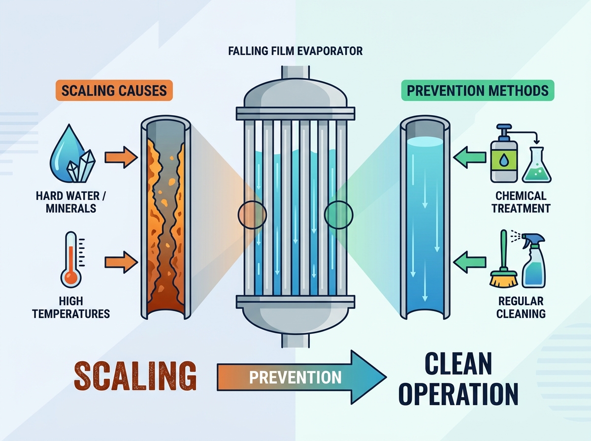
Uneven liquid distribution in falling film evaporators can cause dry spots, localized overheating, and rapid scaling on tube surfaces. Blocked distributor openings, improper leveling, or insufficient liquid flow may disrupt film formation and reduce heat transfer efficiency. Regular inspection of distribution plates, spray nozzles, and liquid levels helps maintain uniform tube wetting, prevent fouling, and ensure stable evaporator performance.
Fluid viscosity increases as water evaporates down the tube length. Increasing viscosity in the lower sections reduces film velocity, meaning the fluid spends more time in contact with the hot wall. Increased residence time leads to severe over-concentration. A boundary layer effect occurs at the liquid-vapor interface where the concentration of solutes exceeds the bulk liquid concentration. This triggers rapid precipitation of dissolved solids directly into the film, which then adhere to the wall.
The physical limits of Falling Film Evaporators are tested heavily here. If viscosity gets too high, the falling film mechanism breaks down completely. The flow regime shifts from turbulent to laminar, and heat transfer drops off a cliff. The fluid becomes too thick to flow smoothly by gravity alone. When you exceed specific viscosity limits, scaling is inevitable. At this point, process engineers must consider forced circulation systems instead.
Evaporator Type | Maximum Practical Viscosity (cP) | Flow Regime | Primary Application |
|---|---|---|---|
Falling Film | 300 - 500 | Gravity-driven turbulent film | Juice, Milk, Low-concentration chemicals |
Forced Circulation | 2000 - 3000+ | Pump-driven high velocity | Crystallization, High-viscosity slurries |
Agitated Thin Film | 50,000+ | Mechanically wiped film | Heavy oils, Polymers, Extreme concentration |
Vacuum leaks and air infiltration can increase evaporator operating pressure, disrupt boiling temperatures, and reduce evaporation efficiency. Common causes include damaged gaskets, loose flanges, and faulty seals. Regular vacuum testing, leak detection, and timely component replacement help maintain stable operation and prevent excessive scaling.
Excessive temperature differences can cause localized boiling, uneven liquid distribution, and accelerated scaling on heat exchanger surfaces. Maintaining an appropriate temperature differential through controlled heating pressure and stable operating conditions helps protect the falling film, improve heat transfer efficiency, and reduce fouling.
Liquid distribution systems ensure uniform wetting across evaporator tubes, reducing dry spots and scaling risks. Gravity distributors, weir plates, and spray nozzles offer different flow characteristics. Proper selection should consider fluid viscosity, operating capacity, and minimum wetting requirements to maintain consistent performance.
Tube material and surface finish influence corrosion resistance, fouling behavior, and cleaning requirements. Titanium and duplex stainless steel provide improved durability in suitable corrosive environments, while electropolished surfaces can reduce particle adhesion. Selecting compatible materials helps extend equipment life, simplify cleaning, and maintain heat transfer performance.
Tube Material | Surface Roughness (Ra µm) | Corrosion Resistance | Best Application |
|---|---|---|---|
304 Stainless Steel | 0.8 - 1.2 | Moderate | Standard dairy, Low-chloride water |
316L Stainless Steel | 0.4 - 0.8 | High | Juice, Mild chemical processing |
Duplex Stainless Steel | 0.4 - 0.8 | Very High | High-chloride environments, Wastewater |
Titanium | 0.2 - 0.4 (Polished) | Extreme | Aggressive acids, Salt crystallization |
Predictive monitoring and automated controls help maintain evaporator efficiency by tracking heat transfer performance, condensate flow, temperature, and feed conditions. Smart systems can detect early fouling, optimize energy consumption, and schedule Clean-in-Place (CIP) cycles before severe scaling occurs, reducing maintenance downtime.
Proper feed flow and recirculation control ensure uniform tube wetting and reduce scaling risks. While higher recirculation rates increase pumping energy, they help prevent dry spots and tube blockage. Flow meters, Variable Frequency Drives (VFDs), and temperature monitoring allow operators to balance energy efficiency, product quality, and reliable evaporator performance.
Implement a strict routine for vacuum decay testing to catch micro-leaks before they disrupt your thermal balance. Audit your liquid distribution plates during the next scheduled shutdown to ensure uniform wetting rates across the entire tube bundle. Upgrade your automation sensors to monitor real-time heat transfer degradation and trigger preventative washes. Review and adjust your CIP chemical concentrations based on the specific type of scale forming in your system. Finally, establish hard operational limits for temperature differentials to prevent nucleate boiling and protect the falling film.
A: The ideal wetting rate depends heavily on tube diameter and fluid viscosity. Generally, it ranges between 0.5 to 2.5 kg/(m·s). Maintaining this specific rate ensures a continuous liquid film, preventing dry spots and localized scaling.
A: CIP frequency varies entirely by application. Dairy plants may require daily CIP due to rapid protein fouling. Chemical plants might run for several weeks. Monitor your overall heat transfer coefficient to determine the exact, optimal cleaning schedule.
A: Yes, if your product viscosity exceeds the physical limits of a falling film design. Forced circulation handles higher concentrations and suspended solids much better, though it requires significantly more pumping energy.
A: Air leaks raise the system pressure, which increases the fluid's boiling point. This forces operators to increase steam temperature, leading to localized overheating and rapid scale deposition directly on the tube walls.
A: Yes. Electro-polishing reduces the microscopic surface roughness of the metal. A smoother surface gives precipitates and organic matter fewer physical anchor points, significantly slowing the rate of scale accumulation.
A: A safe temperature differential usually falls between 3°C and 8°C per effect. Exceeding this range risks initiating nucleate boiling, which destroys the liquid film and bakes solids onto the bare tube wall.
A: Dry spots form when liquid distribution is uneven or the wetting rate is too low. The liquid film ruptures, exposing bare metal. The remaining liquid flashes off instantly, leaving concentrated solutes baked onto the hot surface.

